
Tag: Semiconductor
Introduction
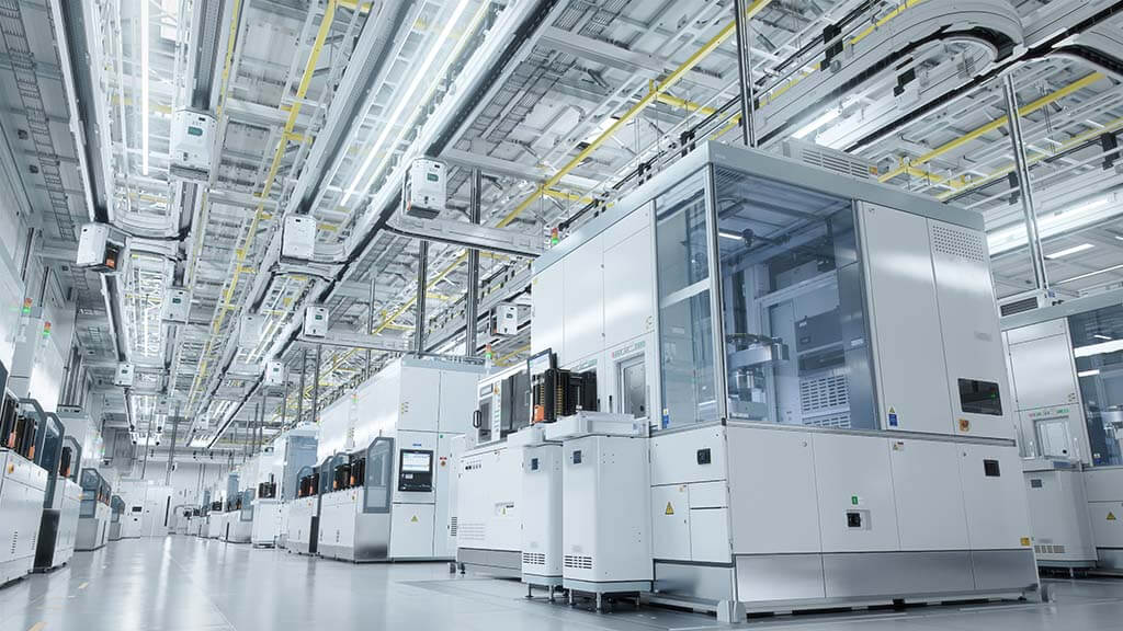
A leading provider of engineering solutions to manufacture microchips needed to address equipment components that were about to reach the end of their life. Rather than replacing the fleet of chip manufacturing machines, the company pursued a more cost-effective solution of upgrading the outdated critical machine components. One of the critical components that needed upgrading was the environmental control unit (ECUs) used to preserve the integrity of each piece of equipment.
Since technology had advanced significantly, leaders at the company were in the market for a modernized drop-in replacement unit and turned to Air Innovations for help. Air Innovations had the depth of experience creating customized, high-performance ECUs they sought.
Challenges
In the time since the original environmental control system was designed, microprocessing power had increased significantly. This made the chips even more sensitive to heat, cold, moisture, and debris. Exposure to an imperfect environment compromises the quality of the manufactured microchips, which impacts how well they function within their devices. The first challenge was to design an ECU that was sophisticated enough to meet even stricter requirements.
The second challenge was designing an ECU that could be retrofitted into a relatively small, pre-existing space. Utility connection points were fixed, the supply of conditioned air had to line up with the original unit, and despite having to ensure more precise environmental control, the unit could not be any larger.
Next, since microchip manufacturing occurred in cleanrooms versus open-air factories, routine equipment maintenance would need to be as easy to execute as possible.
Finally, when a process occurs in a cleanroom environment, equipment breakdowns could stall chip manufacturing production for weeks. The Air Innovations solution needed to be robust.
The Solution
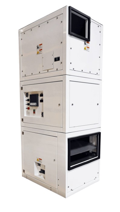
Air Innovations designed a one-ton ECU that met all requirements.
First, the unit could maintain a temperature within +/- 0.05 ℉ (+/- 0.03 ℃) with a temperature setpoint range of 68-79 ℉ (20-26 ℃) and humidity setpoint range of 40-50% +/-1% relative humidity. Since these ranges exceed the client’s expectations, the ECU could provide precise climate control even when microchips get smaller and continue to advance.
The heat exchangers used in the original unit were no longer available, so Air Innovations created a custom one with identical utility connection points. The unit recirculated a constant volume of conditioned, precision-temperature air through external carbon and ULPA filters to control the printhead chamber environment.
The ECU incorporated existing system air inlet and air outlet sizes, shapes, and locations and maintained the existing flow rate and direction of airflow.
It was also designed for zero leakage from all pressurized plenum seams, access covers, and fasteners. To prevent moisture from disrupting the chip manufacturing process, the area around the heat exchanger had a drip tray connected to a drain port designed to function using gravity while the ECU operated. Optical surfaces were placed downstream from the ECU to minimize exposure to out-gassing materials to the unit air stream.
Serviceable components like the motor and belt drive were located out of the main air path with removable shields for easy cleaning. Finally, spherical casters were included on the bottom of the ECU for ease of installation and removal.
Phase Two: Designing and Building From Scratch
The semiconductor equipment manufacturer came back to Air Innovations for a second project. This time, the company was looking for Air Innovations to engineer and build new equipment. While the first drop-in replacement ECU controlled the climate using air, the second project would need to utilize air to maintain the environment and a water component to cool the chip manufacturing equipment.
The solution would need two separate streams that provided precise chilled water to cool and protect the manufacturing process. The lasers that cut materials to make microchips generated a lot of heat and could be air-cooled like the first set of ECUs. The back of the laser, however, needed to be water-cooled.
Second Solution
This time, the Air Innovations team engineered a unit with a closed water loop that circulated from the ECU to the back of the laser. The circulating cold water absorbed the heat generated by the laser motor.
The second stream of water came from the building’s water supply to the heat exchanger to remove the heat from the closed water loop and put it into the air.
The Drop-In Replacement Result:
The environmental control unit included the following:
- Set point range adjustable 68-79 ℉ (20-26 ℃)
- Set point range adjustable 40-50% RH +/-1%
- 1000 SCFM design airflow
- 120 CFM make-up air from the top edge of the ECU return air duct
- 75” +/- 0.10” W.G. external static pressure
- Incoming power at 60 Hz
- Re-circulated conditioned air through external Carbon and ULPA filters
- Noise Level Control less than 65 dba within the assembled chamber
If you’re ready for a custom solution from Air Innovations, like these custom environmental control units, contact us by submitting a Project Inquiry or calling 1-800-835-3268 today.
For case studies on other industries, view our general case studies page. We also have whitepapers covering the aerospace industry, semiconductor industry, and MyZone Systems product line. The whitepaper page can be found here.
